 from the Daylighting screen.
Daylighting calculations are controlled using a set of options on the Daylighting calculation options dialog which is displayed before the calculations are started. To access this dialog (and the Daylighting calculations) press the Update toolbar icon from the Daylighting screen.
Naming the calculation will provide a useful reference for your simulation results. You may wish to include information on any variation made for each calculation.
Select the type/purpose of the simulations that you require. The available options are:
1-General - the default option, for general purpose daylighting calculations when none of the other options 2 - 6 from the list below apply and/or full flexibility is required.
2-LEED - provides access to various types of LEED daylighting calculations from LEED v2 through to v4.1 including option 1 (annual) and option 2 (point in time) simulations when LEED v4 or v4.1 is selected.
3-BREEAM - provides access to BREEAM HEA Options 4a (point in time) and 4b (annual) calculations.
4-LM-83-12 - the option to choose for sDA, ASE and UDI simulations when they are not for LEED or BREEAM.
5-Right to light (BS8206) - provides access to right to light calculations for assessing the impact of new developments on daylight availability in a building. Annual probably sunlight hours (APSH), Vertical sky component (VSC), No sky line (NSL) and Average daylight factor (ADF) reports can be generated.
6-Green star - provides access to the point in time Green star daylight factor calculations and report.
If you do not require any particular report or you require full flexibility in the calculation settings then select 1-General.
Note: Daylight results are stored separately for each Simulation type so you can generate and store multiple results sets, one for each of the above, each using different calculation option settings.
This selection allows you to set the output quality of the simulation. The quality and accuracy increase down the list. For most typical simulations, the 4-Good setting is sufficient.
Selecting a detail template from the drop list loads a set of Radiance settings and ambient parameters to the dialog as shown in the table below.
You do not necessarily need to have an in-depth understanding of the meaning of each of these parameters to carry out an accurate assessment in DesignBuilder. However knowing a little bit about the way the calculations work and how the options affect the calculations will help you to understand how to get the best trade-off between accuracy and simulation times.
| Detail template | |||||
|---|---|---|---|---|---|
| Radiance code | -ab | -aa | -ar | -ad | -as |
|
1-Fast Not recommended for project work |
1 | 0.3 | 128 | 256 | 128 |
|
2-Standard Lowest usable quality - but will underestimate illuminance |
3 | 0.25 | 256 | 512 | 256 |
|
3-Good (no interpolation) |
4 | 0.00 | 512 | 1024 | 512 |
|
4-Good Default setting for balanced accuracy and simulation speed |
4 | 0.22 | 512 | 1024 | 512 |
|
5-Accurate Best setting for highest practical accuracy |
5 | 0.20 | 512 | 2048 | 1024 |
|
6-High quality Use when highest quality is required and a long wait for results is acceptable |
7 | 0.18 | 1024 | 4096 | 2048 |
Tip: For a discussion on the relative merits of using some of the above settings for daylight credit calculations see Guidance for Calculating Daylighting Credits for LEED, BREEAM, Green Star etc.
Enter the height of the working plane above floor level for each zone in the daylight simulation (in m or ft). The default value will depend on the Simulation type selected. The working plane height entered on this dialog corresponds with the building level setting on the Output model data tab.
The working plane height is normally set at the average height of the top surface of the desks above the floor. A typical value will be in the range 0.7-0.8m.
Note: The working plane height used in Radiance calculations is measured from the top of the floor surface level and not the base of block.
Tip: To define different working plane heights for different zones, you can override the building level setting on this dialog by entering values under the Daylighting outputs header on the Outputs model data tab at block or zone level.
This is the smallest grid size that can be used to fill in gaps in the working plane in cases where the maximum grid size is too large, especially at the edges of the plane. Use smaller values (e.g. 0.01m) to fill in most gaps between the main grid cells and the borders of the working plane for a more continuous output. It is common to use a Minimum grid size that is a factor of between 0.5 and 0.1 times the Maximum grid size.
To maintain a uniform grid across the working plane set the Minimum grid size the same value as the Maximum grid size (below).
The main grid size that can be used to divide up the working plane when calculating illuminance. Larger values will speed up calculations but give lower resolution in daylighting outputs.
You should consider the size and number of zones in the building when selecting the grid size. A very fine grid will of course cause Radiance calculations to take a lot longer to complete. On the other hand a very coarse grid in a small zone may not give a good enough distribution.
You should use a maximum grid size no greater than 5ft or 1.5m for LEED daylighting calculations.
If you enter a value greater than zero in this cell, DesignBuilder automatically generates a ground plane below all site objects to model ground-reflected light. The ground plane is generated behind the scenes and its dimensions are calculated by setting up a rectangular box in the plan view around the building extents and adding the Ground plane extension at each edge.
The auto-generated ground plane uses the Ground reflectance defined at site level.
An alternative approach to model ground reflectance is to set the Ground plane extension to zero and to use ground component blocks instead. Or a combination of ground component blocks and the ground plane extension can be used.
Tip: While it may be tempting to enter a very large number here to cover a large area, that is not usually recommended as it would significantly change the scene dimensions used within Radiance. Larger scene dimensions require high detail settings which may require very long simulation times.
Enter the margin (in m or ft) around the zone boundaries where illuminance data is not to be included in summary results. This option can be used to help avoid inclusion of potentially misleading illuminance data close to walls and windows. DesignBuilder sets the default margin depending on the simulation type selected.
If you would like other buildings to be included in the daylighting study as shading/reflecting surfaces then check the Include all buildings checkbox. Note that daylighting results will only ever to generated for the current building.
The whole sky distribution is normalized to the zenith value, so having the sun too near to the zenith could be a problem and therefore Radiance limits the solar position a maximum altitude of 87 degrees. If the calculated solar altitude is higher than this limit then Radiance uses the maximum allowed value of 87 degrees in the calculations. A warning message will be displayed informing this change. Generally this restriction should not impact the daylighting results.
Hemispherical sampling at the first level will always be initiated from the first point supplied to rtrace. From these hemispherical sampling rays, the ambient calculation will predict the way the indirect irradiance is changing about that point (the indirect irradiance gradient). The calculation also evaluates an estimation of error associated with the prediction for the irradiance gradient. These quantities, together with the Ambient accuracy parameter, are used to determine a “radius of validity” for the gradient estimate. If the next point supplied to rtrace is within this radius, the indirect irradiance is evaluated from the gradient estimate and not from further hemispherical sampling. In other words, the value is obtained by a form of interpolation rather than by actual sampling.
Irradiance interpolation can occur across the points supplied to rtrace, so hemispherical sampling at the first level will not necessarily be initiated from every point in the working plane supplied to rtrace.
It is important to appreciate the element of chance at work whenever hemispherical sampling is used. If the number of initial sampling rays were set too small, the calculation might, for example, miss a bright patch even though it was visible from the point at which the rays were spawned. Likewise, an unrepresentative chance “hit” of a small bright patch by one of the sampling rays can produce a gross overestimate for indirect irradiance. In a rendering, the artefacts associated with ambient undersampling can cause bright and dark blotches.
To minimise blotches we need to set a sufficiently high value for the number of initial sampling rays, Ambient divisions. Hemispherical sampling is generally too expensive to initiate at every surface visible from the eye point. The calculation needs good indirect irradiance estimates from sampling at a limited number of locations. We then rely on the irradiance interpolation algorithm to estimate missing values. To generate a fairly smooth rendering for a daylight calculation accounting for the first level of inter-reflection, we would need to set moderately high resolution values for the ambient parameters.
Each Simulation type has a different set of calculation options and you can find help for each in topics below.
The following options are available on the Daylight Calculation Options Dialog for static illuminance and annual CBDM simulations. They govern the quality of the simulation and are best set through the Detail template by non-expert users.
The number of ambient bounces is the maximum number of diffuse bounces computed by the indirect calculation. The number of ambient bounces that Radiance should apply varies depending on the type of building and daylighting system you are analysing. It can be set based on the number of reflections typically required by the light to reach the task plus one or two extra for inter reflection within the space.
The number of bounces should normally be set to 3 for most accurate calculations or 2 if some trade-off is acceptable. 4 does not usually add much accuracy over and above 3 and 1 and 0 are inadequate for most daylighting calculations.
Note: When the number of ambient bounces is set to 0 the ambient lighting calculations are switched off, so only direct sun/sky light patches are considered.
Tip: It is possible to calculate the fraction of the working plane which receives direct sunlight by setting the Ambient bounces calculation option to 0 and the Illuminance threshold display option to 0, then viewing the Floor Area above Threshold data in the Grid output.
If the number of ambient bounces is set to 1, light is considered to reach the interior surfaces from the sun's direct rays, from the diffuse sky, and from first bounce reflections of direct sunlight rays from both interior and exterior surfaces. Reflections of sky light off interior or exterior surfaces to other interior surfaces will not be considered. Additional bounces can be added to consider additional flux paths.
Note that a value of 3 for the number of ambient bounces is often enough for daylight factor calculations. However, if the daylight factor plot is "lumpy", setting a higher value alone will not fix it.
Doubling ambient bounces can double rendering time.
Ambient accuracy (-aa) is the maximum error (expressed as a fraction) permitted in the indirect irradiance interpolation.
You should normally use a value between 1 and 0.1, with lower values giving the best accuracy. A value of zero gives no interpolation.
Halving Ambient accuracy approximately quadruples rendering time.
The Ambient resolution sets the distance between ambient calculations by determining the maximum density of ambient values used in interpolation. Factors that influence the scale over which interpolation may occur are:
The minimum possible spacing between hemispherical indirect irradiance sampling points is the maximum scene dimension multiplied by the ambient accuracy divided by the ambient resolution. In other words, for distances less than this minimum, the calculation will always resort to interpolation, rather than initiate more sampling, regardless of the error estimate associated with that interpolation. This prevents the calculation from spending unnecessary time resolving irradiance gradients over negligible scales. This distance gives the scale at which the interpolation accuracy begins to deteriorate from the ambient accuracy setting. The minimum separation for calculated irradiances, Smin, is:
Smin= Dmax × Ambient accuracy / Ambient resolution
Where the scene dimension, Dmax, is a measure of the maximum dimension of the zone being treated.
The effect of increasing Ambient resolution depends on the scene but it can quadruple calculation times for double the value.
Ambient divisions sets the number of initial sampling rays sent from each ambient point into the hemisphere to determine the indirect incident light. The error in the Monte Carlo calculation of indirect illuminance will be inversely proportional to the square root of this number. A value of zero implies no indirect calculation.
The Ambient divisions and super-samples parameters can be used to help reduce "noise" in a calculation. By setting these options higher more rays will be tested when calculating an ambient value for a point.
High values of this parameter (4096 is perhaps the highest value that would be used under normal circumstances) will minimise "patchiness" of daylighting outputs but slow calculations. Doubling Ambient divisions will approximately quadruple calculation time.
The number of extra rays that will be used to sample areas in the divided hemisphere that appear to have high variance. Ambient super sampling should usually be set to about one half or one quarter of the Ambient divisions parameter. Super-samples are applied only to the ambient divisions which show a significant change.
The effect of increasing Ambient super-samples is to reduce "patchiness" in regions where indirect illuminance is changing rapidly, but adding to the Ambient divisions and calculation times.
Some general advice on the approach is:
When this option is selected Radiance uses Monte Carlo random sampling during the simulations which causes results for each simulation to have small variations. In other words you will see small differences in results each time you run the same simulation. To ensure that results are consistent between simulations you should leave this option unchecked.
In daylighting simulations, the sky is broken up (discretised) into a number of "patches". The more finely the sky is discretised, the more accurate the daylighting results and longer the simulations will take.
This option is used in all Annual daylighting simulations and in No Sky Line Right to Light calculations.
Important Note: For No Sky Line Right to Light calculations you should select the greatest available detail, option 6-5185.
You can select the number of sky patches that will be used from the options listed below:
1-145 - the original Tragenza sky discretised into 145 patches. 
2-577 - sky is discretised into 577 patches. This is the default option corresponding to Reinhart’s extension of the Tregenza sky, where the original 145 patches are subdivided into 4 subpatches, except at the zenith. MF:2 Reinhart subdivision scheme.
3-1297 - sky is discretised into 1297 patches. MF:3 Reinhart subdivision scheme.
4-2305 - sky is discretised into 2305 patches. This corresponding to Reinhart’s extension of the Tregenza sky, where the original 145 patches are subdivided into 16 subpatches, except at the zenith. MF:4 Reinhart subdivision scheme.
5-3601 - sky is discretised into 3601 patches. MF:5 Reinhart subdivision scheme.
6-5185 - sky is discretised into 5185 patches. MF:6 Reinhart subdivision scheme.This is the most detailed option and is recommended for use with the No sky line Right to Light calculation which requires a fine sub-division of the sky for accurate results.
In annual daylighting simulations, the position of the sun at any particular timestep is approximated to lie on a grid of Sun patches. This option allows you to define the granularity of the grid.
This setting is used in all Annual daylighting simulations.
1-145 - the original Tragenza sky discretised into 145 patches.
2-577 - sky is discretised into 577 patches. This is the default option corresponding to Reinhart’s extension of the Tregenza sky, where the original 145 patches are subdivided into 4 subpatches, except at the zenith. MF:2 Reinhart subdivision scheme.
3-1297 - sky is discretised into 1297 patches. MF:3 Reinhart subdivision scheme.
4-2305 - sky is discretised into 2305 patches. This corresponding to Reinhart’s extension of the Tregenza sky, where the original 145 patches are subdivided into 16 subpatches, except at the zenith. MF:4 Reinhart subdivision scheme.
5-3601 - sky is discretised into 3601 patches. MF:5 Reinhart subdivision scheme.
6-5185 - sky is discretised into 5185 patches. MF:6 Reinhart subdivision scheme.This is the most detailed option.

Illustration of the Sun patch concept. Each of the above images is a fisheye rendering for the solar positions corresponding to a particular value of MF (Radiance parameter defining the number of subdivisions for each Tregenza patch). The sky discretisation is shown with red dots and the actual positions of the sun for every hour of the year are shown as white lines. Clearly the greater the number of Sun patches, the more accurate the solar position in the simulations.
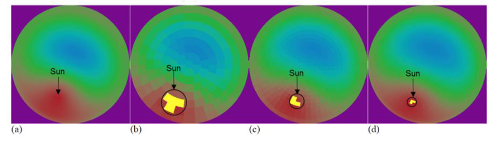
The above image shows fish-eye projections of a continuous sky model (a) along with corresponding discretised versions. Images (b), (c) and (d) use 145, 580 and 2305 sky patches respectively. The images show that even with a high degree of discretisation, the size of the sun is overestimated in discrete sky models as the actual position of the sun in the sky at a given time is approximated to 3-4 sky patches. Clearly, this approximation in position is accompanied by an overestimation of the size of the sun with respect to the sky.
Enter the maximum number of cores that DesignBuilder should use for the Radiance simulations. Enter 0 to use all cores. Note that if you allocate all cores to Radiance, your machine may not be sufficiently responsive to allow you to work on other tasks while the simulations run.