This tutorial will help you get up to speed with running a changeover mixed mode natural ventilation study in a few easy steps.
In general, mixed mode controls can be used with either Calculated or Scheduled natural ventilation, Simple or Detailed HVAC. This tutorial demonstrates the process for the Simple HVAC and Scheduled natural ventilation model options as the easiest way to learn how to apply the mixed mode settings.
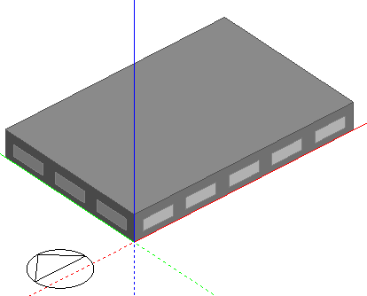
Start by creating a new file located in London Gatwick and add a building to the site with a simple rectangular block having dimensions 30m x 20m as shown below. Use default Model options.
In Simple HVAC mode, HVAC components are controlled using the Model data inputs on the Activity and HVAC tabs. The following steps describe the settings required on these tabs.
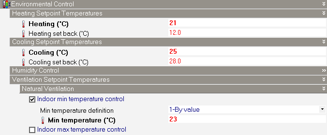
To prevent simultaneous operation of the cooling and natural ventilation systems, the setpoint temperatures must be defined carefully. The recommended deadband between natural ventilation and heating/cooling is 2°C.
In this example, these setpoint temperatures should be entered as follows:
Heating setpoint: 21°C
Cooling setpoint: 25°C.
The Activity tab, Environmental Control settings should now look like this:
By default, DesignBuilder will load the “Fan Coil Unit” HVAC template in new models. For this example, you should change that by navigating to building level, clicking on the HVAC model data tab and loading the “Radiator heating, Boiler HW, Mixed mode Nat Vent, Local comfort cooling” HVAC Template.
Set the maximum natural ventilation rate to 3 ac/h.
Select the “Winter heating (Northern Hemisphere)” Heating Operation Schedule to ensure that heating is switched off in summer.
The HVAC tab should now look something like the screenshot below:
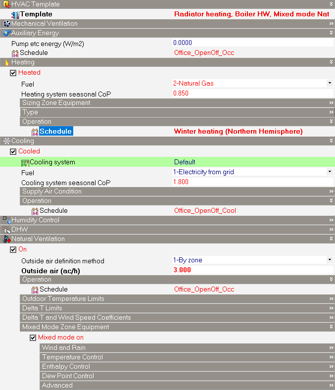
Note that the heating, cooling, natural ventilation and mixed mode controls are all switched on.
DesignBuilder provides a set of Mixed Mode Zone Equipment settings to allow various detailed aspects of the system to be controlled, as shown below.
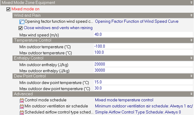
For this tutorial you can use the defaults.
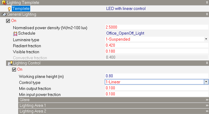
To ensure that lighting internal gains are consistent with a modern naturally ventilated building, a more efficient system than the default “Reference” template should be loaded.
At building level, go to the Lighting tab and select the “LED with linear control” Lighting template.
The data on the Lighting tab should now be as below.
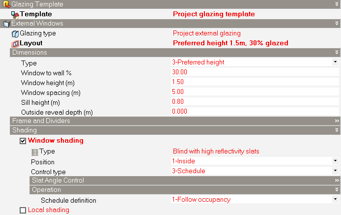
Similarly, to ensure that solar gains are kept in check and consistent with a modern naturally ventilated building, some window shading should be introduced.
At building level, go to the Openings tab and check the Window shading checkbox. By default, this will provide high reflectivity internal blinds for all windows.
The data on the Openings tab should now be as below.
We are now ready to run a test simulation.
Go to the Simulation screen and press the Update toolbar icon to open the Simulation Calculation options dialog.
Click on the "Summer typical week" Info panel link to load simulation dates for the typical summer week for this location.
Check the Sub-hourly Output Interval for Reporting to help you check the correct operation of the system.
On the Options tab, select the 6 Timesteps per hour option.
Press OK to run the Simulation.
Select the 5-Sub-hourly Interval in the Display options bottom left panel and review the results.
You should see graphs similar to those below.
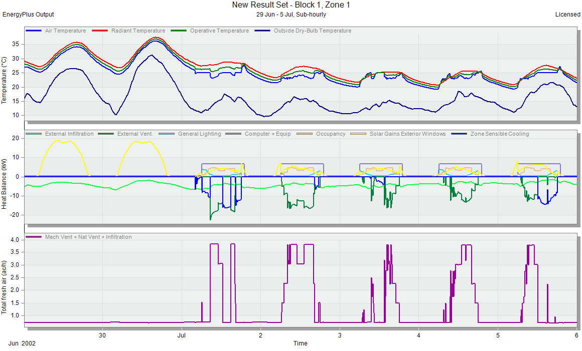
The temperature graph shows that, during the working week, the inside air temperatures are controlled to be between 23 and 25°C during occupied periods. Temperatures are controlled to 23°C when natural ventilation is active, but when natural ventilation cannot meet the cooling demand, mechanical cooling is activated to maintain temperatures below 25°C.
The heat balance graph shows that cooling (blue line) and natural ventilation (green line) occur independently (never simultaneously) to meet the cooling load as required.