This tutorial explains the process involved in setting up a Parametric analysis using Custom Script variables to modify the shading configuration in a model by loading various façade configurations from a series of XML files. Each shading configuration to be tested in the parametric simulations is set up in the model by adding component blocks and saving them in an external XML file. A simple Python script loads the appropriate XML file to the model for each parametric custom variable configuration.
This approach to parametric modelling is ideal for investigating and optimising shading systems that have more complex or non-standard shapes than can be modelled using the Local shading mechanism,
The main learning points are:
How to save a series of component block files in XML format to represent each shading configuration to be tested.
Writing a simple Python script to load the XML files as required during the parametric simulations.
Secondary learning points re-enforce points from the more basic optimisation custom script variable tutorial:
1. Create a new model located at London Gatwick.
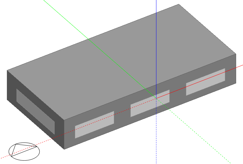
2. Add a building using default settings and draw a rectangular block measuring 20m by 10m with block height of 3.5m as shown below.
3. Delete the windows on the north, east and west façades.
4. Load the Generic Office Area Activity template at building level on the Activity Tab (if it is not already selected).
In this step we will create 3 XML files to represent 3 of the 4 anticipated variable options:
No overhang (no file to be loaded)
0.5m overhang
1.0m overhang
1.5m overhang
To create the 3 files follow these steps. All these steps should be carried out at building level.
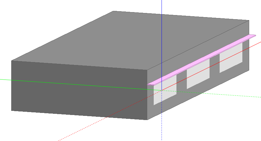
1. Draw a component block above the windows on the south façade to represent the 0.5m overhang case. The model should look like this.
2. Select the component block and save it as an XML file using the File > Export > Export selected component blocks as XML menu command. Use the name "Overhang 0.5m.xml".
3. Now increase the depth of the overhang to 1.0m. You can use the Drag face command to do this.
4. As before, select the component block and save it as an XML file. Use the name "Overhang 1.0m.xml".
5. Now increase the depth of the overhang to 1.5m and follow the same procedure as above to save the XML file to represent the 1.5m overhang.
You should now have a list of 3 XML files:
Overhang 0.5m.xml
Overhang 1.0m.xml
Overhang 1.5m.xml
6. It would be good practice to import the XML files manually to check that everything is in order before the parametric runs. Use the File > Import > Import component blocks from XML menu command to do this. You will need to delete the original component block first to allow the component blocks to be imported from file. Intersection checks will prevent the parametric XML imports if the component block is left there.
Make a note of where you have saved these files and be sure to set this folder name in the XML_DIR variable in the script that we will write in the next step.
7. The final and essential task is to delete the overhang component block to allow the XML files to be imported during the parametric runs. As mentioned above, intersection checks will prevent the parametric XML imports if the component block is left there.
To define the parametric analysis follow these steps.
Step 3.a - Open the Parametric, Optimisation and UA/SA Analysis Settings dialog by clicking on the  toolbar icon.
Step 3.b - On the Analysis type tab set the Analysis type to 1-Parametric analysis.
Step 3.c - On the Outputs tab add the Output results for the parametric analysis study. We will be using cooling electric energy as the KPI for this analysis:
Click on the Add Output Info panel link.
On the Analysis Outputs dialog select the Cooling Electricity Output KPI under the "Energy and Loads" category and enter the name as "Cooling Elec Energy". Press OK. The Outputs tab should now look like this: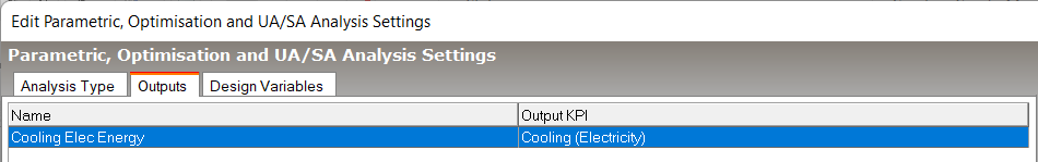
Step 3.d - On to the Design Variables tab.
Delete all but one variable from the list by selecting each in the grid in turn and pressing the Delete variable Info panel link.
You should now have only 1 item Design Variables list.
Select it and click on the Edit variable Info panel link.
On the Edit Analysis Variables dialog select the "Custom Script" Variable type under the "Custom script" category heading. Press OK.
Under the Range header set the Min value to 0 and the Max value to 1.5. This will alllow us to test overhangs of between 0 and 1.5m length.
Under the Increment Step header set Step (parametric) to 0.5 to ensure that we test the overhangs in 0.5m steps, i.e. overhang values of 0, 0.5, 1.0 and 1.5m will be tested. You could set Step (optimisation) to 0.5 as well although we don't plan to run an optimisation study in this example.
The Variable key is not used in this analysis and can be left blank.
Set the Name of the design variable to "Overhang".
Note: The name entered here on the Edit Analysis Variables dialog must match the corresponding name used in the custom script described below. You may like to copy the name and paste it somewhere safe where you can easily access it later when writing the script.
Press OK to close the Analysis variables dialog and return to the Design Variables tab of the Parametric, Optimisation and UA/SA Analysis Settings dialog, which should now look like this: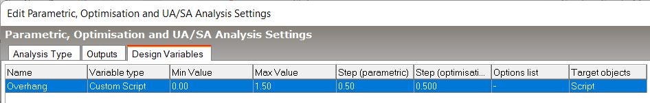
Follow the steps below to set up the Python script for the analysis.
1. Click on the Scripts  toolbar icon to open the Script Manager dialog and click on the Enable scripts checkbox.
2. Click on the Script browse item. A list of the existing scripts appears in the Info panel to the right.
3. Click on the Python-Script category and press the Add  Info panel icon to create a new Python script.
4. Change the name of the script to "Overhang Custom Variable". This is for your convenience and does not need to match with any other settings.
5. Edit the script to apply the overhang settings to the model as follows:
import os
import ctypes
def show_message(title, text):
ctypes.windll.user32.MessageBoxW(0, text, title, 0)
XML_DIR = r"C:\Users\<USERNAME>\Documents\DesignBuilder Data"
def on_design_variable_changed(opt_var_id, variable_current_value):
site = api_environment.Site
table = site.GetTable("OptimisationVariables")
record = table.Records.GetRecordFromHandle(opt_var_id)
opt_variable_name = record["Name"]
if opt_variable_name == 'Overhang' and float(variable_current_value) > 0:
overhang_length = "{:.1f}".format(float(variable_current_value))
xml_name = "Overhang {}m.xml".format(overhang_length)
xml_path = os.path.join(XML_DIR, xml_name)
if os.path.exists(xml_path):
active_building.ImportComponentBlocksFromXMLFile(xml_path)
else:
show_message("Error", "Cannot find xml file: '{}'.".format(xml_path))
Tip: To save time you can copy the above script and paste it into the dialog. Note that Python requires the indentation as part of its syntax and when you paste the above script the indents may become lost. In this case you must insert the indents manually after the paste. The easiest way to do that it by using the <Tab> key.
Note: If you copy the above script you will need to change XML_DIR to define the path on your machine where the XML files have been saved.
The on_design_variable_changed hook point is called once for each variable when the model is being prepared for the simulation. The value of opt_variable_name, passed in via opt_var_id, defines the variable being handled and the value of variable_current_value also passed in provides the value of this variable for this simulation. The script simply loads the appropriate XML file depending on the variable_current_value.
active_building in this case is a reference to the parametric clone copied from the base model for each simulation and so it is safe to apply any parametric changes to it without affecting the base model.
6. Check the Enable program checkbox to ensure that the script will be executed at runtime.
7. Press OK to confirm the changes to the script.
Click on the Simulation tab and press update to run a base annual simulation as a necessary step before running the optimisation. Before pressing OK, You should make the following settings:
1. Ensure you are running simulations for the whole year by clicking on the Annual simulation Info panel link.
2. Ensure you are generating only Annual/Monthly results by checking the Monthly and Run period interval and that all other outputs are switched off.
Leave all other settings in their default state.
Navigate to the Parametric tab and press the Update toolbar icon to open the Calculation Options dialog and run the parametric analysis simulations. Accept default settings and press the Start button.
The 4 simulations should run through quickly and when they have finished press the Close button to return to the main screen.
After the parametric analysis simulations have completed and you have closed the Calculation Options dialog, the main screen should look similar to the screenshot below.
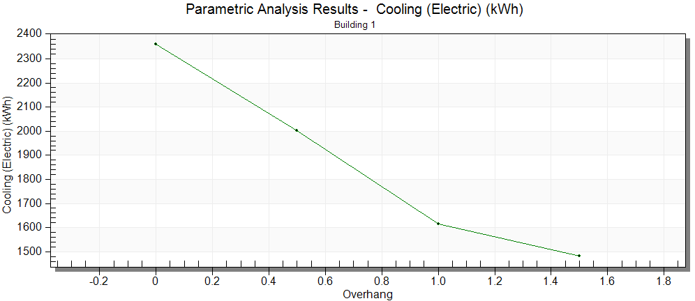
Results show diminishing returns as the overhang extends from 1.0m to 1.5m.
Note: The tutorial demonstrates how to test the impact of various rectangular shading overhangs on building cooling energy. To help focus on the main learning points the shading case being modelled is a very simple one that could actually have been implemented more easily using the Local shading overhang mechanism. However note that much more geometrically complex shading configurations can also be tested through a process very similar to the one demonstrated in this tutorial.